Friday, August 27, 2010
Java concurrency guidelines
An extensive report on Java concurrency guidelines - by Fred Long et al. and published by SEI-CMU recently - can be found here.


Thursday, August 05, 2010
Eponymous laws
Eponymous laws are adages, laws, principles, theorems, etc. named after a person. Wikipedia has a fabulous list of such laws here.
A few from the above list (taken as is) that may be of interest to folks in software engineering:
A few from the above list (taken as is) that may be of interest to folks in software engineering:
- Amara's law — "We tend to overestimate the effect of a technology in the short run and underestimate the effect in the long run."
- Brooks' law — "Adding manpower to a late software project makes it later." Named after Fred Brooks, author of the well known book on Project Management, The Mythical Man-Month.
- Campbell's Law - "The more any quantitative social indicator is used for social decision-making, the more subject it will be to corruption pressures and the more apt it will be to distort and corrupt the social processes it is intended to monitor." Named for Donald T. Campbell (1916 - 1996)
- Classen's law — Theo Classen's "Logarithmic Law of Usefulness" - 'usefulness=log(technology)'.
- Conway's Law — "Any piece of software reflects the organizational structure that produced it." Named for Melvin Conway.
- Dilbert Principle — Coined by Scott Adams as a variation of the Peter Principle of employee advancement. Named after Adams' Dilbert comic strip, it proposes that "the most ineffective workers are systematically moved to the place where they can do the least damage: management."
- Gall's law — "A complex system that works is invariably found to have evolved from a simple system that worked."
- Gibrat's law — "The size of a firm and its growth rate are independent."
- Godwin's law — An adage in Internet culture that states, "As an online discussion grows longer, the probability of a comparison involving Nazis or Hitler approaches one." Coined by Mike Godwin in 1990.
- Goodhart's law — "When a measure becomes a target, it ceases to be a good measure."
- Kranzberg's First Law of Technology — "Technology is neither good nor bad; nor is it neutral."
- Linus' law — "Given enough eyeballs, all bugs are shallow." Named for Linus Torvalds.
- Murphy's law — "Anything that can go wrong will go wrong." Ascribed to Edward A. Murphy, Jr.
- Pareto principle — States that for many phenomena 80% of consequences stem from 20% of the causes. Named after Italian economist Vilfredo Pareto, but framed by management thinker Joseph M. Juran.
- Rothbard's law — "Everyone specializes in his own area of weakness."
- Sayre's law — "In any dispute the intensity of feeling is inversely proportional to the value of the stakes at issue."
- Wirth's law — "Software gets slower faster than hardware gets faster."
- Dunning-Kruger Effect - Per this Wikipedia article: "... is a cognitive bias in which an unskilled person makes poor decisions and reaches erroneous conclusions, but their incompetence denies them the metacognitive ability to realize their mistakes. The unskilled therefore suffer from illusory superiority, rating their own ability as above average, much higher than it actually is, while the highly skilled underrate their abilities, suffering from illusory inferiority".
Saturday, July 10, 2010
Computer and software history
Cicero (Roman author, orator, & politician - 106 BC - 43 BC) is quoted to have said: "History is the witness that testifies to the passing of time; it illumines reality, vitalizes memory, provides guidance in daily life and brings us tidings of antiquity."
For those interested in the history of computers: The Computer History museum, located here on the Web, is dedicated to preserving and presenting the stories and artifacts of the information age. It was established in 1996 in Mountain View, California, USA. Also checkout videos of the many lectures and events at the museum and historic computer films, hosted on Youtube.
The museum has a special interest group on software history. Besides the history of software since the 1950s it has interesting anecdotes, first person essays, etc.
Keep in mind though, the Website is still in the making.
For those interested in the history of computers: The Computer History museum, located here on the Web, is dedicated to preserving and presenting the stories and artifacts of the information age. It was established in 1996 in Mountain View, California, USA. Also checkout videos of the many lectures and events at the museum and historic computer films, hosted on Youtube.
The museum has a special interest group on software history. Besides the history of software since the 1950s it has interesting anecdotes, first person essays, etc.
Keep in mind though, the Website is still in the making.
Friday, July 02, 2010
Rift between business and IT
Found this particularly hilarious picture on one of Anne Thomas Manes' slides set (don't remember which one though).


Thursday, July 01, 2010
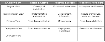
Mappings Among Architecture View Sets
This is my take on how some of the popular view sets map to each other:

Friday, June 11, 2010
"Selling" and "Order Handling" Overview (Communications Service Provider Environment)
I often get queries related to basic aspects of selling and order handling business processes from teams that I work with. Here is a brief (very brief) overview of these processes, using TeleManagement Forum's Business Process Framework (widely known as eTOM) as a reference.
In sales terminology, a potential or a likely customer is called a "prospect". Prospects are typically determined by one of the following:

g) Manage sales accounts: This sub-process is responsible for managing sales accounts assigned to a sales channel and/or manager [Etom_Gb921]. These accounts are then used on a regular basis to develop appropriate relationships and contacts, to prospect for leads for other offerings, or to offer specific discounts based on criteria such as sales volume, length of relationship, etc.

2. Order Handling
Once a sales contract has been signed by the customer, its time to create and process customer orders for fulfilling the services that form the product offering. Enter order handling.
Although the terms product offerings and services are often used interchangeably, they have separate meanings. As described by [McFadyen], "This is best thought of as the box that everything is put in. Just as when you buy cornflakes it is the flakes of corn you want inside the box, but it is the box with its logo, brand name, and barcode that you actually purchase." The "flakes of corn" is the service while the "box of cornflakes" is the product offering. From the viewpoint of a product manager, a product offering defines what functionality is provided at what price to which market segments over which sales channel. A service on the other hand is the functionality that the customer gets. Product offerings can get complex in that many different services may be combined in a single offering bundle to make it attractive (cost-effective, for e.g.).
eTOM classifies key order handling processes/activities as:

The sub-processes within order handling are:
a) Determine preorder feasibility – This sub-process is responsible for determining whether the standard/customized product offering chosen for the customer is available and/or feasible. Examples of such checks include (but are not limited to):
c) Issue customer order – This sub-process ensures that all necessary information about the customer order is captured and validated and that the customer has been issues a sales order. This sub-process typically kicks in after a purchase order has been received by the service provider.
A purchase order (PO) is a commercial document issued by a buyer to a seller, indicating types, quantities, and agreed prices for products or services the seller will provide to the buyer [Wikipedia_po], and constitutes a legal offer to buy products or services. Acceptance of the PO by the seller (service provider in this context) forms a contract between the buyer and the seller. A PO ensures the service provider is protected in case of a customer's refusal to pay for agreed products or upon unilateral cancelling of the order [Wikipedia_po].
A sales order (SO), on the other hand, is an order issued by the seller (service provider in this context) to the buyer (customer). Information captured as part of the sales order may include originating PO (one or more), service locations, product configuration data (such as bandwidth, circuit speed, etc.), bill-to customer account, customer contacts, and so forth. Both the customer and the service provider use the issued order to track the status, make edits to the order, etc.
d) Track and manage customer order handling – The objective of this sub-process is to ensure customer provisioning activities are assigned, managed and tracked efficiently to meet the committed availability date [Etom_Gb921]. This includes scheduling activities, generation of respective service order creation requests, tracking orders, adding additional information to existing customer order, cancelling customer order, monitoring jeopardy status of customer orders and escalating customer orders as necessary [Etom_Gb921].
e) Complete customer order – This process is responsible for ensuring that any customer information required by any other processes is updated as part of customer order completion [Etom_Gb921]. This may involve additional touch points with the customer. This may also involve sending relevant notifications to the customer on events such as service provider's acceptance of the order, commitment date, etc.
f) Report customer order handling – The objective of this sub-process is to monitor the status of customer orders, provide notifications of any changes and provide management reports [Etom_Gb921]. Specialized notifications to customers may include those indicating service provider's validation and acceptance of the order, availability date of the services, completion of the provisioning, activations of the respective services, etc.
g) Close customer order – The objective of this sub-process is to close a customer order when the customer provisioning activities have been completed.
As mentioned earlier, eTOM doesn't specify how the sub-processes are sequenced.
References
[McFadyen] Andrew McFadyen, http://telecomseim.blogspot.com/
[Etom_Gb921] GB921 Addendum D-Process Decompositions & Descriptions, Business Process Framework (eTOM), R 8.0, TeleManagement Forum (TM Forum), June 2009
[Wikipedia_po] http://en.wikipedia.org/wiki/Purchase_order
[TargusInfo] "Turning Prospects into Profits", TargusInfo, 2009
1. Selling
In sales terminology, a potential or a likely customer is called a "prospect". Prospects are typically determined by one of the following:
- Leads – These are typically determined by product marketing teams and decision analytics systems supporting product marketing. For e.g., responses from email-, direct- or tele-marketing campaigns may provide good leads to potential customers. Similarly, website analytics tools may be used to analyze web page hits from a particular region to determine prospects.
- Referrals – The customer might indicate an interest to a branch or call center representative who then directs the referral to sales specialists. Service providers also provide customer portals where customers can register an interest.
- Transaction-Based Triggers – Prospects may also be determined by transaction-based activities combined with decision analytics. For e.g., based on customer's long distance calling pattern and its availability to a sales rep, the sales rep may be able to suggest a higher value unlimited long distance plan.
Prospects are turned into opportunities for further processing through the sales-pipeline, based on a number of factors, including but not limited to [TargusInfo]:
- Which prospects are most likely to convert?
- What is a prospect's potential lifetime value?
- What size order would the prospect place if she were to become a customer?
The sales-pipeline supports the key selling related functions such as analysis of customer needs, identification of respective product offerings, sales-negotiation, quotes, proposals, sales forecast, etc. eTOM classifies key selling sub-processes as illustrated in Figure 1 below.

The sub-processes within "Selling" in eTOM are:
a) Manage prospect: This sub-process is responsible for matching assigned leads with the most appropriate products and ensuring that the prospects are handled appropriately [Etom_Gb921]. Activities include capturing and processing the probability of successful sales closure, estimating the total attainable revenue, analyzing the needs of the prospect, identifying potential solutions from the service provider's portfolio, etc.
b) Qualify opportunity: This sub-process ensures that the opportunity is qualified in terms of any associated risk, and the amount of effort required (e.g., response to a RFP vs. potential revenue) to achieve a sale [Etom_Gb921]. Also, customer's needs are analyzed and matched against available product offerings or customized solutions.
c) Negotiate sales/contract: Customers may agree with the standard prices and promotions or may want to negotiate pricing. For example, although the sales rep may have already offered 5% discount, the customer might be looking for a 12% discount. Also, the customer may want to negotiate non-standard terms and conditions/contracts. This sub-process includes activities supporting sales and contract negotiation.
d) Acquire customer data: This involves collection, association and organization of all pertinent data related to the customer, including those that are required to support the agreed product offerings and contract.
e) Cross/up selling: The purpose of this sub-process is to ensure that the value of the relationship between the customer and service provider is maximized by selling additional, or more of the existing products [Etom_Gb921]. Additionally, the ongoing analysis of customer's usage, problems or complaints can be used to identify when the current products may no longer be appropriate for the customer, or an opportunity for a larger sales arise [Etom_Gb921].
f) Develop sales proposal: The purpose of this sub-process is to develop a sales proposal to respond to customer's requirements [Etom_Gb921]. The development of a sales proposal may require selection of standard a product offering or may require the development of a non-standard offering [Etom_Gb921], leading to development of a unique solution design.
Note that the sub-processes defined in eTOM, as shown in Figure 1 above, are in no particular sequence. eTOM refrains from defining sequencing of these processes as different service providers may need to implement them in different sequences, based on their particular environment. Figure 2 below depicts a sample flow that might be applied in a service provider environment.

Once a sales contract has been signed by the customer, its time to create and process customer orders for fulfilling the services that form the product offering. Enter order handling.
Although the terms product offerings and services are often used interchangeably, they have separate meanings. As described by [McFadyen], "This is best thought of as the box that everything is put in. Just as when you buy cornflakes it is the flakes of corn you want inside the box, but it is the box with its logo, brand name, and barcode that you actually purchase." The "flakes of corn" is the service while the "box of cornflakes" is the product offering. From the viewpoint of a product manager, a product offering defines what functionality is provided at what price to which market segments over which sales channel. A service on the other hand is the functionality that the customer gets. Product offerings can get complex in that many different services may be combined in a single offering bundle to make it attractive (cost-effective, for e.g.).
eTOM classifies key order handling processes/activities as:

The sub-processes within order handling are:
a) Determine preorder feasibility – This sub-process is responsible for determining whether the standard/customized product offering chosen for the customer is available and/or feasible. Examples of such checks include (but are not limited to):
- Can the corresponding services be provisioned at the given location?
- Are there enough circuits or lines available in the given region?
- Can the services meet the specified SLA based on current network environment?
c) Issue customer order – This sub-process ensures that all necessary information about the customer order is captured and validated and that the customer has been issues a sales order. This sub-process typically kicks in after a purchase order has been received by the service provider.
A purchase order (PO) is a commercial document issued by a buyer to a seller, indicating types, quantities, and agreed prices for products or services the seller will provide to the buyer [Wikipedia_po], and constitutes a legal offer to buy products or services. Acceptance of the PO by the seller (service provider in this context) forms a contract between the buyer and the seller. A PO ensures the service provider is protected in case of a customer's refusal to pay for agreed products or upon unilateral cancelling of the order [Wikipedia_po].
A sales order (SO), on the other hand, is an order issued by the seller (service provider in this context) to the buyer (customer). Information captured as part of the sales order may include originating PO (one or more), service locations, product configuration data (such as bandwidth, circuit speed, etc.), bill-to customer account, customer contacts, and so forth. Both the customer and the service provider use the issued order to track the status, make edits to the order, etc.
d) Track and manage customer order handling – The objective of this sub-process is to ensure customer provisioning activities are assigned, managed and tracked efficiently to meet the committed availability date [Etom_Gb921]. This includes scheduling activities, generation of respective service order creation requests, tracking orders, adding additional information to existing customer order, cancelling customer order, monitoring jeopardy status of customer orders and escalating customer orders as necessary [Etom_Gb921].
e) Complete customer order – This process is responsible for ensuring that any customer information required by any other processes is updated as part of customer order completion [Etom_Gb921]. This may involve additional touch points with the customer. This may also involve sending relevant notifications to the customer on events such as service provider's acceptance of the order, commitment date, etc.
f) Report customer order handling – The objective of this sub-process is to monitor the status of customer orders, provide notifications of any changes and provide management reports [Etom_Gb921]. Specialized notifications to customers may include those indicating service provider's validation and acceptance of the order, availability date of the services, completion of the provisioning, activations of the respective services, etc.
g) Close customer order – The objective of this sub-process is to close a customer order when the customer provisioning activities have been completed.
As mentioned earlier, eTOM doesn't specify how the sub-processes are sequenced.
References
[McFadyen] Andrew McFadyen, http://telecomseim.blogspot.com/
[Etom_Gb921] GB921 Addendum D-Process Decompositions & Descriptions, Business Process Framework (eTOM), R 8.0, TeleManagement Forum (TM Forum), June 2009
[Wikipedia_po] http://en.wikipedia.org/wiki/Purchase_order
[TargusInfo] "Turning Prospects into Profits", TargusInfo, 2009
Thursday, May 13, 2010
Paul Graham on Startups
Paul Graham is famous for his plain-spoken, deeply insightful and thought-provoking essays. Some of his essays on startups:
- "What Startups are Really Like"
- "How to Start a Startup"
- "The Hardest Lessons for Startup to Learn"
- "How to fund a Startup"
- "Ideas for Startup"
- "The 18 Mistakes that Kill Startups"
- "A Fundraising Survival Guide"
Tuesday, May 11, 2010
Saturday, May 01, 2010
Bjarne Stroustrup on what should be taught to new software developers in college
Bjarne Stroustrup's article titled "What Should We Teach New Software Developers? Why" (Communications of the ACM, Vol. 53 No. 1, Pages 40-42 ).
Tuesday, April 27, 2010
Tuesday, April 06, 2010
TM Forum's MTOSI standard: Setting the Context
MTOSI stands for Multi-Technology Operations Systems Interface. It is a standard specified by TM Forum. It is now part of TM Forum's Interface Program (TIP).
Why is it called "multi-technology"? Why do you need to worry about it? What does it really do? How does it relate to other TM Forum standards and initiatives (often, quite confusing for starters!)? This article attempts to explain the answers for these questions.
This article is organized as follows:
The intent of TeleManagement Forum's (TMF) Multi-Technology Operations Systems (MTOSI) is to provide open and standards-based interfaces between OSSs (e.g., Service Activation systems, Inventory systems, Network Management Systems, Element Management Systems, etc.). For a detailed exploration of OSS/BSS systems, see my earlier post titled "Telecom OSS/BSS: An Overview".
2) Related TM Forum Standards
2.1 Relationship with MTNM
TeleManagement Forum's (TMF) Multi-Technology Operations Systems Interface (MTOSI) started as an MTNM (Multi-Tehchnology Network Management) substream sometime in 2003. Lets discuss MTNM first.
MTNM provides CORBA-based Element Management Layer (EML)-to-Network Management Layer (NML) interfaces for the management of "multi-technology" networks (SONET, SDH, PDH, ATM, Frame Relay, DSL, connectionless networks such as Ethernet, etc.). However, it can also be used to support a single technology such as ATM. Examples of management areas are: connection management, NE and EMS configuration, network inventory discovery, euqipment inventory management, performance monitoring, alarm surveillance and event reporting, etc. MTNM can also be used to manage a particular subset of a management area - say, alarm surveillance.
Around the time MTNM 3.5 commenced, it was realized that several vendors were using MTNM by converting the CORBA IDLs to XMLs, due to lack of XML based interfaces. Enter MTOSI.
MTOSI has gradually taken sets of MTNM interfaces, generalized the operations systems to operations systems interactions and created XML, SOAP Web services based interfaces - recasting and extending MTNM. Like MTNM, it provides a single interface for the management of many technologies. Moreover, MTOSI has had the goal to make XML interfaces independent of the underlying transport (HTTP, JMS, etc.)
2.2 Relationship with TIP and mTOP
MTOSI has been part of TM Forum Interface Program (TIP) since April 2008. Multi Technology OSS Program (mTOP) coordinates advances in the SOAP and XML based MTOSI interface standard, as well as the CORBA/IDL based MTNM standard. MTOSI service classifications are based on the eTOM model, while the information model is based on SID and MTNM data models.
2.3 Comparision with OSS/J
MTOSI APIs are focused towards providing interfaces at the service, network and element management layers. OSS/J on the other hand aims to provide open interfaces across the spectrum of both OSS and BSS. OSS/J APIs, unlike most MTOSI APIs are network technology independent [1]. OSS/J APIs are entity centric unlike MTOSI APIs that are task-centric. OSS/J provides a generic set of operations on "Managed Entities" [1]. There are efforts underway to draw the OSS/J and MTOSI communicaties together, and we may see a common goals and plans for migration for both OSS/J and MTOSI in the future.
3) Motivation
Element Management Systems (EMS) typically manage the functions of Network Elements (switches, CPU and remote hubs, gateways, routers, susbcriber line units, etc.) from a single vendor. Examples of such management functions include receiving and executing commands sent by upstream activation systems, feeding equipment status data back to upstream systems such as network and trouble management systems, etc. Moreover, the EMS may be able to manage functions related to a single technology (e.g., ATM, SONET, etc.) for a subset of management area (e.g., performance monitoring). Therefore a service provider environment typically has several types of EMS. Typically a Network Management System (NMS) manages functions of many EMSs. To be easily portable across different NMS systems, an EMS vendor can provide MTOSI based standards interface. This would enable easy integration of the EMS with various NMS that service providers could use.
Lets consider another example. A service activation system (an OS) may allow an order management system (also an OS), to request activation of a given service via a service request. The service activation system (an OS) may in turn need to send requests to multiple NMS and EMS OS's to complete the service activation request. A service provider environment in all likelihood contains multiple service activation systems as well as multiple EMS's. If each of those provided proprietary interfaces containing proprietary information models: a) the order management system must be integrated with each of the service activation interfaces, and b) the service activation systems must be integrated with the relevant EMS interfaces. With many services being added on frequent basis, this can easily turn into a nightmare. Utilizing standards-based interfaces provided by MTOSI the integration becomes lot more easier, reducing costs and increasing agility.
Lets consider yet another example. Say, an operator uses Telcordia TIRKS system to administer Layer 1 facilities and equipment while it uses a seperate OSS inventory system to administer Layer 2/3 (logical inventory) and higher services. TIRKS provides an open interface (data dictionaries and XML message definitions) using MTOSI which can be used by the OSS inventory systems to receive messages generated by TIRKS systems (such as inventory update notifications) and to send messages to the TIRKS system.
Similarly, a fault managent system may need to subscribe to alarm reports based on filtering conditions and may also handle subsequent reporting of alarms to subscribed OSs. Similarly, a manager fault management system may receive alarms from several technology-specific fault management system via active alarm sync.
4) MTOSI Description
MTOSI defines OS-to-OS (OS stands for operations systems) interfaces for service and resource management, where OS functionality can be at the levels of Element Management Layer, Network Management Layer or the Service Management layer, in the Telecommunications Management Network (TMN) Logical model.
Examples of such OS in this context include: Inventory Management, Performance Management Systems, Fault Management Systems, Service Activation, Service Assurance, CRM systems such as Order Entry system, Network Management systems, Element Management Systems (EMS). Refer to my earlier post titled "Telecom OSS/BSS: An Overview" for a description of some of these.
Note, that MTOSI is not concerned with EMS-to-NE API, which is typically based on protocols such as SNMP, TL or CMIP. Nor is it concerned with internal implementation details such as an internal inventory model - it only provides a data format and a number of operations around retrieving or modifying the data.
Management functions covered by MTOSI include (but not limited to):
[1] "Bridging the Gap Between MTOSI and OSS/J" by Nigel Davis, John Reilly and Suresh Bhandarkar
[2] "Implementing NGOSS with MTOSI"
[3] "A very short history of mTOP" (Requires login to TM Forum site)
[4] Tim McElligott, "MTOSI brings OSS Integration a Step Closer", Nov 2005,
[5] "Designing a Standards-Based Application", March 2009,
[6] Stephen Fratini, Irene McGoey, Garry Grimes and Enrico Grosso, "Introduction to the TM Forum's Multi-Technology Network Model", National Fiber Optic Engineers Conference, 2001
Why is it called "multi-technology"? Why do you need to worry about it? What does it really do? How does it relate to other TM Forum standards and initiatives (often, quite confusing for starters!)? This article attempts to explain the answers for these questions.
This article is organized as follows:
- Section "1 - Intent" provides a summary of what MTOSI aims to do.
- Section "2 - Related TM Forum Standards" provides a description of how MTOSI is related to some of the other TM Forum standards and initiatives.
- Section "3 - Motivation" provides scenarios that illustrates the problem(s) MTOSI addresses.
- Section "4 - MTOSI Description" provides more details on MTOSI.
The intent of TeleManagement Forum's (TMF) Multi-Technology Operations Systems (MTOSI) is to provide open and standards-based interfaces between OSSs (e.g., Service Activation systems, Inventory systems, Network Management Systems, Element Management Systems, etc.). For a detailed exploration of OSS/BSS systems, see my earlier post titled "Telecom OSS/BSS: An Overview".
2) Related TM Forum Standards
2.1 Relationship with MTNM
TeleManagement Forum's (TMF) Multi-Technology Operations Systems Interface (MTOSI) started as an MTNM (Multi-Tehchnology Network Management) substream sometime in 2003. Lets discuss MTNM first.
MTNM provides CORBA-based Element Management Layer (EML)-to-Network Management Layer (NML) interfaces for the management of "multi-technology" networks (SONET, SDH, PDH, ATM, Frame Relay, DSL, connectionless networks such as Ethernet, etc.). However, it can also be used to support a single technology such as ATM. Examples of management areas are: connection management, NE and EMS configuration, network inventory discovery, euqipment inventory management, performance monitoring, alarm surveillance and event reporting, etc. MTNM can also be used to manage a particular subset of a management area - say, alarm surveillance.
Around the time MTNM 3.5 commenced, it was realized that several vendors were using MTNM by converting the CORBA IDLs to XMLs, due to lack of XML based interfaces. Enter MTOSI.
MTOSI has gradually taken sets of MTNM interfaces, generalized the operations systems to operations systems interactions and created XML, SOAP Web services based interfaces - recasting and extending MTNM. Like MTNM, it provides a single interface for the management of many technologies. Moreover, MTOSI has had the goal to make XML interfaces independent of the underlying transport (HTTP, JMS, etc.)
2.2 Relationship with TIP and mTOP
MTOSI has been part of TM Forum Interface Program (TIP) since April 2008. Multi Technology OSS Program (mTOP) coordinates advances in the SOAP and XML based MTOSI interface standard, as well as the CORBA/IDL based MTNM standard. MTOSI service classifications are based on the eTOM model, while the information model is based on SID and MTNM data models.
2.3 Comparision with OSS/J
MTOSI APIs are focused towards providing interfaces at the service, network and element management layers. OSS/J on the other hand aims to provide open interfaces across the spectrum of both OSS and BSS. OSS/J APIs, unlike most MTOSI APIs are network technology independent [1]. OSS/J APIs are entity centric unlike MTOSI APIs that are task-centric. OSS/J provides a generic set of operations on "Managed Entities" [1]. There are efforts underway to draw the OSS/J and MTOSI communicaties together, and we may see a common goals and plans for migration for both OSS/J and MTOSI in the future.
3) Motivation
Element Management Systems (EMS) typically manage the functions of Network Elements (switches, CPU and remote hubs, gateways, routers, susbcriber line units, etc.) from a single vendor. Examples of such management functions include receiving and executing commands sent by upstream activation systems, feeding equipment status data back to upstream systems such as network and trouble management systems, etc. Moreover, the EMS may be able to manage functions related to a single technology (e.g., ATM, SONET, etc.) for a subset of management area (e.g., performance monitoring). Therefore a service provider environment typically has several types of EMS. Typically a Network Management System (NMS) manages functions of many EMSs. To be easily portable across different NMS systems, an EMS vendor can provide MTOSI based standards interface. This would enable easy integration of the EMS with various NMS that service providers could use.
Lets consider another example. A service activation system (an OS) may allow an order management system (also an OS), to request activation of a given service via a service request. The service activation system (an OS) may in turn need to send requests to multiple NMS and EMS OS's to complete the service activation request. A service provider environment in all likelihood contains multiple service activation systems as well as multiple EMS's. If each of those provided proprietary interfaces containing proprietary information models: a) the order management system must be integrated with each of the service activation interfaces, and b) the service activation systems must be integrated with the relevant EMS interfaces. With many services being added on frequent basis, this can easily turn into a nightmare. Utilizing standards-based interfaces provided by MTOSI the integration becomes lot more easier, reducing costs and increasing agility.
Lets consider yet another example. Say, an operator uses Telcordia TIRKS system to administer Layer 1 facilities and equipment while it uses a seperate OSS inventory system to administer Layer 2/3 (logical inventory) and higher services. TIRKS provides an open interface (data dictionaries and XML message definitions) using MTOSI which can be used by the OSS inventory systems to receive messages generated by TIRKS systems (such as inventory update notifications) and to send messages to the TIRKS system.
Similarly, a fault managent system may need to subscribe to alarm reports based on filtering conditions and may also handle subsequent reporting of alarms to subscribed OSs. Similarly, a manager fault management system may receive alarms from several technology-specific fault management system via active alarm sync.
4) MTOSI Description
MTOSI defines OS-to-OS (OS stands for operations systems) interfaces for service and resource management, where OS functionality can be at the levels of Element Management Layer, Network Management Layer or the Service Management layer, in the Telecommunications Management Network (TMN) Logical model.
Examples of such OS in this context include: Inventory Management, Performance Management Systems, Fault Management Systems, Service Activation, Service Assurance, CRM systems such as Order Entry system, Network Management systems, Element Management Systems (EMS). Refer to my earlier post titled "Telecom OSS/BSS: An Overview" for a description of some of these.
Note, that MTOSI is not concerned with EMS-to-NE API, which is typically based on protocols such as SNMP, TL or CMIP. Nor is it concerned with internal implementation details such as an internal inventory model - it only provides a data format and a number of operations around retrieving or modifying the data.
Management functions covered by MTOSI include (but not limited to):
- Inventory Retrieval, Inventory Update Notifications, Enhanced Inventory Retrieval (attribute value matching based on XPath), Multi-Event Inventory Notifications (ability to send multiple inventory updates in a single notification)
- Alarm Reporting, Active Alarm Retrieval
- Service Activation
- Service Inventory Management
- Resource configuration and activation
- Performance management and maintenance commands
- Multi-Action and Request Transactions (MART) (i.e., ability to package multiple requests into a single message)
- TMF 518, MTOSI Business Aggreement (BA): Identifies the requirements and use cases to be supported by the interface.
- TMF 612, MTOSI Information Aggreement (IA): UML description of the interface.
- TMF 864, MTOSI Interface Implementation Specifications (IIS): Maps the UML model to XML (WSDL, XSD, bindings, etc.)
- Supporting documentation
[1] "Bridging the Gap Between MTOSI and OSS/J" by Nigel Davis, John Reilly and Suresh Bhandarkar
[2] "Implementing NGOSS with MTOSI"
[3] "A very short history of mTOP" (Requires login to TM Forum site)
[4] Tim McElligott, "MTOSI brings OSS Integration a Step Closer", Nov 2005,
[5] "Designing a Standards-Based Application", March 2009,
[6] Stephen Fratini, Irene McGoey, Garry Grimes and Enrico Grosso, "Introduction to the TM Forum's Multi-Technology Network Model", National Fiber Optic Engineers Conference, 2001
Thursday, April 01, 2010
On patterns of software degeneration
Here ("Big Ball of Mud" by Brian Foote and Joseph Yoder) is a paper that explains some patterns of software entropy.
Wednesday, March 24, 2010
REST in practice and Richardson's RESTful maturity model
Jim Webber, Savas Parastatidis and Ian Robinson presented "REST in Practice" at a QCon talk, in which they also presented a model of RESTful maturity developed by Leonard Richardson.
Here (Richardson Maturity Model: steps toward the glory of REST) is Martin Fowler's explanation of the maturity model.
Here (Richardson Maturity Model: steps toward the glory of REST) is Martin Fowler's explanation of the maturity model.
Friday, March 19, 2010
Telecom OSS/BSS: An Overview
1. Introduction
Before the initial 1970s, most of the support activities in a telephone company such as taking orders, maintaining network inventory, provisioning services (for example, line assignment and testing), configuring network components, managing faults and collecting payments were performed manually. It was realized that many of these activities could be replaced by computers. In the next few years, a number of computer systems and software applications were created to automate these activities. Examples include TIRKS, RMAS, SES, etc. Thus came the term Operations Support Systems (OSS).
2. The Realm of OSS/BSS in Order Fulfillment, Assurance and Billing
2.1 Order Fulfillment
Communications products/services could range from Voice services to IP and Data services to Hosting and CPE services. Some of the examples of communications products/services are:

After order entry, validation and submission, orders are decomposed and sent for provisioning. Upon fulfilling the decomposed orders and appropriate testing of the circuits, the orders are put into inventory. The following sub-sections explain the Order Fulfillment related functions and OSS/BSS systems.
2.1.1 Order Management
Order Management systems are complex systems that allow customer or customer service representatives to capture and process new orders, modify existing orders, process customer moves and changes, price quotes and orders, validate orders, etc., while supporting multiple channels such as Web, Order template documents and partner applications as well as multiple lines of businesses.
Order Management includes the following areas:
2.1.2 Service Provisioning
Service Provisioning systems are systems used to setup products/services for the customer after an order for the services has been created and accepted by the CSP.
Service provisioning activities include specifying the pieces of equipment and parts of the network to fulfill the service, configuring the customer’s routing path, allocation of bandwidth in the transport network, setting up of wiring and transmission, etc.
Some of the systems that constitute provisioning systems are: Circuit Design & Assignment Tools, Activation systems, and Field Service Management systems.
Circuit design refers to specifying whether facilities exist to provide the service and which pieces of the network equipment and routes the service shall utilize.
One of the most widely used systems providing Circuit Design facility is Telcordia TIRKS. Apart from Circuit Design support, it also provides circuit order control, inventory record maintenance, selection and assignment of components from inventory, and preparation and distribution of circuit work orders. The order control module in TIRKS works with a circuit provisioning system and operates in conjunction with other TIRKS components to assign facility and equipment information for circuit orders and design circuits. TIRKS can then provide automated design criteria for certain circuit orders. The circuit design generated in TIRKS is then communicated to field operations or automated activation systems for implementation.
Circuit Design and Assignment tools these days often have graphical tools that allow a user to create services on a network map using mouse clicks and drag-and-drop rather than drawing maps by hand or using an abstract set of equipment identifiers displayed in a table.
After a service is designed based on the existing equipment and circuit inventory, it is ready to be activated. If new equipment or lines need to be configured manually, a Field Service Management (FSM) system is notified which in turn dispatches technicians.
Moreover, certain activations can be performed automatically. For example, issuing commands to ATM or circuit switches to provision circuits, to SONET terminals to allocate bandwidth, and to a wide array of access devices such as DSLAMS, Digital Loop Carriers (DLC), or cable modems. For such activations, Service Activation systems pass the device specific commands and configuration changes to the network elements, Element Management Systems (EMS), Network Management Systems (NMS) or application hosts.
EMSs are designed to receive and execute commands sent by activation systems on the devices. EMSs can also feed equipment status data back to network and trouble management systems. EMSs use protocols such as Common Management Information protocol (CMIP) or Transaction Language (TL) or Simple Network Management Protocol (SNMP) to communicate with activation and other systems.
Activation systems often comprise a library of adapters to various network systems. They usually also support transaction control, i.e. the capability to roll-back operations already performed, in case an error occurs.
It should be noted that Provisioning systems interact with the Inventory systems, both to verify that the required network elements and other facilities are available, and once the resources are provisioned - to reflect the changed on-line configuration of the facilities. Therefore, provisioning systems have close channels with inventory systems. As a result, some vendors have combined workflow capabilities with inventory management capabilities in their products.
2.3 Inventory Management
Tracking inventory involves tracking equipment, facilities and circuits.
Some examples of information tracked are: the location and quantities of the equipment, how a piece of equipment is configured and its status, etc.
Inventory Management Systems track both the physical network assets (such as equipment and devices) as well as “logical” inventory (such as active ports, circuit ids, IP addresses, etc.), although not all support both.
By relating usage of network assets to specific customers and services, an inventory system can help network operations determine the network usage and available capacity as well as enable automated network design and planning. Inventory Management Systems also enable Service Assurance systems to find the impact of a network fault on the customer’s circuits.
Some tools also have “auto-discovery” features to automatically check physical network assets and match the results with the information held in the inventory. However, these work only with some of the newer intelligent network elements.
2.2 Service Assurance
Communications service providers (CSP) strive to differentiate themselves from their competitors by implementing attractive Service Level Agreements (SLA). SLAs are formal contracts where the level of service delivered by the CSP to his customer is stipulated. An SLA may specify levels of service availability, performance, operation, etc. as well as penalties upon violation of the SLA.
Offering SLAs implies that the service provider has the ability to monitor, act and report the level of service, in order to assure the quality of services delivered to the customers. Service Assurance refers to all the activities performed for such an assurance. The goal of Service Assurance is to provide an optimal customer experience, that helps retain existing customers, attract new customers and prevent penalties arising out of violation of SLAs.
The following sub-sections introduce some of the common service Assurance systems.
2.2.1 Fault and Trouble Management
Fault Management Systems are designed for detection, isolation and correction of malfunctions in a communications network. They monitor and process network alarms generated by network elements (routers, switches, gateways, etc.). An alarm* is a persistent indication of a fault that is cleared only when the triggering condition is resolved.
Examples of trouble or fault in a network are damage to an optical fiber line, switch failure, etc. Such a problem in the network can result in a chain reaction where many network elements in a certain path produce alarms*.
Fault Management Systems may be either a component within Network Management Systems or as a standalone set of system and application software.
The following figure illustrates how fault management works.

Network Elements are designed to provide various levels of self-diagnosis. Older Network Elements might simply send an alarm notifying a problem while newer Network Elements can provide more precise and detailed messages. Fault Management Systems may collect alarms via SNMP traps, CMIP events or proprietary agents, via EMS. They use complex filtering systems to assign alarms to specific severity levels and correlate different alarms to locate the source and cause of a problem.
After a problem is identified, the FMS then notifies appropriate network operators as well as pass the problem information to a Trouble Management System that in turn logs the problem and issues a trouble ticket to start the repair process.
The Trouble Management System then sends commands to appropriate systems such as Field Service Management to schedule and dispatch technicians to repair the equipment and/or to EMS to reroute network traffic around the problem areas.
Trouble Management systems also handle automatic escalation, such as progression of a ticket from minor to major or major to critical, etc., and support a variety of notification methods such as paging, emails, synthesis voice dial-out.
Fault Management systems usually provide graphical network displays which are projected on large screens at the Network Operations Centres (NOC). NOC operators can see role-based views on their consoles, shortcuts to operations they perform the most as well as tools to quickly make connections to EMS to perform any testing or diagnostic operation.
2.2.2 Network Performance Management
Performance Management components in NMS and other Alarm Handlers monitor applications and systems and collect performance variables of interest at specified intervals. Performance variables of interest may be service provider network edge availability, customer premises availability, response times, packet delivery rate, packet losses, latencies, jitters and out of sequence packet reorder, etc., to name a few.
One way to capture performance metrics is collecting event logs, CDRs and other performance data such as counters or timers that the network and system elements maintain as part of their normal operation. This is referred to as passive measurement. Performance data is captured by polling MIB using SNMP or using syslog, (I & II), FTP, EMS feeds, etc. Most passive measurements report on a single network element.
For example, an Ethernet Switch may have a MIB which provides in and out data volumes of each port, histograms of frame sizes, number and types of erroneous frames, central processing unit (CPU) busy status. Associated Remote Monitoring (RMON) MIB-type data can then list ten most active users, etc. Performance Management tools can access the data by using SNMP to poll the MIBs at predefined intervals.
Statistics on performance variables can also be captured via dedicated network appliances known such as “probes” and “sniffers” that monitor or probe customer’s local loop connections, packet performance, etc. This form of performance testing is usually referred to as active testing.
Packet sniffers typically monitor signaling protocols such as SIP and RTP by inspecting packets on the wire/fiber, using pings, DNS, FTP, HTTP fetches, etc. Examples include WireShark and Geoprobes.
Probes such as Brix Networks BrixWorks Verifiers and Tektronix/Minacom IVR tools typically emulate customer traffic in order to test or probe specific paths to measure the quality of the services supported. Probes could be either placed into the network or could be built into network elements such as in the case of Cisco’s IP Service Level Agreements tools.
Note that active measurement measures a service, such as application response time, instead of the internal operation of a network element.
An example of active network performance test is injecting “ping” (short, network layer echo packet) into the network aimed at a remote IP address. Round-trip time is measured if the ping packet returns, and an error counter is incremented if it doesn’t.
Performance statistics captured by “active” or “passive” performance tests are normalized and routed to relational databases and/or data-warehouses. An alternative is to pass the performance data directly to Performance Management tools. For example, Concord eHealth could collect performance statistics from Netcool agents via SNMP polls at a pre-defined interval.
Performance statistics are initially analyzed to determine the normal (baseline) levels. Appropriate thresholds are determined for each of the interesting performance variable so that exceeding the thresholds indicates a problem.
Performance Management tools then measure the performance variables against SLAs defined as thresholds per application or service, on an on-going basis. In case of exceptions they report them to alarm handlers. This form of performance monitoring is reactive performance monitoring. Some tools also support proactive monitoring by way of providing simulation tools that helps network operators project how growth in network traffic will affect performance metrics and plan to take proactive countermeasures such as increase capacity.
Performance Management tools may also support real-time and historical reporting. Some CSPs have taken performance statistics of the network affecting customers’ circuits to their customer self-service portals.
2.2.3. Topology & Configuration Management
Older networks and systems were static and the network wiring was fixed in place, and sometimes required long outages while changes to the network and its configuration were being made. Any error or inconsistency in the configuration files of different network devices caused problem, and therefore these changes were well controlled [3].
According to [3], with the rise of IP-based, dynamically routed networks, network topologies started becoming dynamic. The topology of the network became dynamic because a few of routers might decide, on their own, to shift routing patterns, or because a network operator group might add a new router or switch to the network, possibly without everyone else in the network operations center being aware of the changes. Instead of static associations between users and network addresses (as was set in the old “hosts” file), DHCP and other techniques allowed users to appear, move, and disappear without providing prior notice to the network administration.
Most major NMSs therefore provide capabilities to automatically discover a network’s actual topology, which is critical to understand network performance or root cause of network alarms, etc.
Probes are placed into the network to automatically find devices and circuits. Also, most network elements provide MIBs that can be polled via SNMP to discover the network, although discovering the network topology in its entirety may not be guaranteed. Backup paths, virtual private networks, MPLS, etc., can make it very difficult to discover actual paths, through multiplexed links, patch panels, and test equipment [3].
Also, most Topology Management Systems allow the network operator to provide hints so that the system, for instance, in order that the system can ignore certain portions of the network. This makes it easier to discover relevant portions of the network more accurately.
Some service providers may run network discovery routines on a daily basis to discover any unauthorized changes to the network topology as a result of security intrusions or unplanned insertion of devices.
Moreover, network elements and computer systems have a variety of version information associated with them. For example, a workstation may have: Operation System, version 32, Ethernet Interface, version 5.4, TCP/IP Software, version 2.0 and SNMP Software, version 3.1. Since multiple engineers/network operators work on making changes to the network equipment, tracking the changes manually would be very tedious and error-prone. Configuration Management tools help automates the tracking of the changes. Configuration Management systems store the configurations in a database or LDAP server for easy access.
They also enable network operators to change configurations of the network elements as well as to roll back a change to a previous configuration, if required.
When a problem in the network occurs, network operators often search the Configuration Management database for clues that can help solve the problem.
2.2.4. Planning & Testing
Network Planning solutions help determine when a communication network needs an upgrade or additional equipment as well as to predict the impact of changes to a service provider’s network’s topology, configuration, traffic and technology. They provide simulation tools that help the network operators to project how growth in network traffic will affect the network performance. Based on the results and other planning activities, network operators can take countermeasures such as increase capacity.
Testing is an important activity in setting up a network or customer circuits. For simplicity in understanding the gamut of testing activities, let us divide them into the following:
1. Testing of existing network or a change
2. Integration testing of services configured for the customer
3. End-to-end testing of services configured for the customer
Testing the entire network platform - including the equipment, services and call quality – is critical for assessing the system prior to deployment and for service assurance in production environments [4].
Network testing tools usually simulate a production environment and generate synthetic voice, video and data traffic, which helps measure call/data quality, network performance, and the affects of any changes to the network or increasing traffic or adding new applications. These tests typically include tests like DNS, HTTP, RTP, Ping, etc. Also, during ongoing operations, these testing tools enable active testing of facilities.
Another form of testing is integration testing of network setup for the customer, i.e., routes, circuits, etc. configured for a customer. Network operators or field engineers perform integration testing of services upon completion of activations and other provisioning activities. Field engineers typically use equipment and network element specific applications to perform integration testing.
Upon completion of integration testing, field operations teams are notified to perform end-to-end testing. End-to-end testing includes testing of circuits, both within the CSP’s network as well as local access circuits between the CSP and the customer premises. Some service provider’s use craft access systems for the benefit of field technician’s access to their internal systems through a hand held terminal [5]. The hand held terminal helps them to access loop testing system and to view the complete test summary from remote locations.
2.3 Billing
IDC [6] defines Billing as: the processing and compiling of charges and enabling of revenue collection for network usage, feature transactions, and access charges of the services.Mediation systems collect network usage data from the network elements and convert to billable statistics.
The following figure depicts a simple Billing flow:

Traditionally, for phone calls, Call Detail Records (CDR) have been used to record the details of the circuit-switched phone call. CDR includes information on start time of call, end time of call, duration of call, originating and termination numbers. CDRs are stored until a billing cycle runs. For IP Based Services, a new standard is gaining acceptance called Internet Protocol Detail Record (IPDR). IPDR supports both voice and data.
Billing systems use mediation output to determine charges for the customers. It is also used to feed other downstream applications such as Fraud and Churn Management.
2.3.2 Rating
Rating systems calculate the charge for an individual call, IP usage event, etc. using the CDRs/IPDRs. Rating systems apply charges based on pre-configured pricing rules, applicable discounts and rebates from promotions.
This rating process has grown increasingly complex in recent years. In older times, it was solely a matter of taking the length of the call, assigning a price based on the mileage band (calculated by cross-referencing the prefix of the originating and terminating numbers in a table of values), and assigning discounts based on the time of day (peak, evening, night), day of the week, and holidays.
Modern rating systems can assign discounts based on calling circles, provide flexible rating plans based on size of accounts and increase switching costs [2]. These serve as strategic marketing tools but can be very complex to administer and operate.
2.3.3 Billing Systems
Billing systems aggregate rated calls, IP/data usage events, etc. and calculate customer invoices. In the United States, billing is usually performed once a month.
Billing systems combine rated records with prior balance information, payment records, recurring charges (such as line rentals), one-time fees (such as installation and service charges), promotions and discounts associated with the customer account, taxes and credits. Overnight billing batch jobs are among the largest batch environment at a CSP’s operating environment. Each customer is assigned a specific billing cycle.
According to Insight [2], the holy grails of the billing industry are unified billing and convergent billing. With unified billing, a customer gets a single bill for all services provided (or billed) by the service provider, appropriately rated, discounted, and taxed, and a single contact for inquiries and negotiation.
2.3.4. Interconnection Billing
In the competitive world of communications, service providers often tie-up with partners, in order to bundle their own products with their partners. This helps the service providers to provide attractive bundles of products and services. However, in order to successfully settle interconnect billing settlements an effective Interconnection Billing is required.
Interconnection Billing products support inter-working of a service provider’s billing systems with the corresponding systems of another service provider, based on interconnect agreements and contracts.
2.3.5. Revenue Assurance
Revenue Assurance & Fraud Management systems verify billing, detect and identify unauthorized usage of service provider network assets. Some of the kinds of frauds are Usage and Subscription.
Usage Fraud means that a customer uses the telecommunications network illegally. This is accomplished either by obtaining a service with no intent to pay or by obtaining unauthorized access to the network (i.e. “hacking” or “cracking”).
Fraud Management systems typically detect and prevent unauthorized access to a communications network by analyzing traffic patterns on the network. Some examples are provided in [8]:
Detecting subscription fraud involves searching recent order and existing customer data for multiple orders and/or accounts with the same customer name, SSN, or service address.
Common subscription fraud patterns include:
Fraud Management Systems typically read and store usage data from the service provider’s network switching equipment and allows queries to be executed against the data that detect suspicious usage patterns.
They also allow operators to review customer accounts that have suspicious activity, to track their investigation and record the final case resolution.
It should be noted that fraud is different from revenue leakage. Revenue leakage is characterized by the loss of revenues resulting from operational or technical loopholes where the resulting losses are sometimes recoverable and generally detected through audits or similar procedures [1]. Fraud, on the other hand, is characterized with theft by deception, typically characterized by evidence of intent where the resulting losses are often not recoverable and may be detected by analysis of calling patterns.
Another important class of Revenue Assurance tools includes Churn Management tools. Churn management is an important area for service providers that have subscription-based business - due to price wars, aggressive marketing and promotions from competing service providers, and customer’s expectations related to customer service.
Churn Management tools provide functions such as automated behavior analysis, forecasting and simulation, empirical profiling, churn metrics capture, that enable service providers to learn which customers are likely to leave and take appropriate countermeasures.
3. Conclusion
3.1 Summary
OSS/BSS systems and applications automate many of the day to day operations performed in a communications service provider’s operating environment. They optimize the time taken to perform these operations and make the business processes more efficient.
There are no all-encompassing OSS/BSS systems that can be installed, integrated, tested and allow the service providers to easily modernize their end-to-end operations functions.
Service providers, therefore, use all the different approaches: best-of-breed in some areas, off-the-shelf in some, and home-grown custom applications in the remaining areas, to modernize and optimize their operations.
More often than not, many of these OSS/BSS systems are integrated with the others in a point-to-point fashion, as part of discrete projects and programs, sponsored out of different business units. This leads to point-to-point integration of OSS/BSS systems unless the programs/projects are planned with a strategic goal.
A side effect of the difficulty in integrating the various OSS/BSS systems is many of the OSS/BSS systems in a service provider’s operating environment may not be integrated at all. For example, it is not unusual to find the following scenario: when a customer orders a new telephone line, the ordering system takes the details of a customer’s order, but a manual process is present to configure the telephone exchange using a switch management system. Details of the order entered in the Order Handling system is re-keyed manually by the technician into the Switch Management System – a process often referred to as “Swivel-Chair Integration”.
The article provided an overview of some of the core OSS/BSS areas in Order Fulfillment, Service Assurance and Billing.
3.2 References
[1] Who Makes What: OSS, http://www.lightreading.com/document.asp?doc_id=113052&print=true, Light Reading, Dec 2006
[2] The 2007 Telecommunications Industry Review, The Insight Research Corp., Dec 2006
[3] Eric Siegel, Architectural Overview of Network Management, The Burton Group, Oct 2005
[4] Arindam Banerjee, Network Management is the Key to the Success of Next-Generation Architecture, Yankee Group, Jan 2007
[5] Senthil K. Ramachandran, Order Fulfillment Core Processes and Pain Areas, TMFC 2122 White-paper
[6] Sterling Perrin et al., IDC's Service Provider Infrastructure Taxonomy, 2004, IDC
[7] Lars Andersson, OSS Solutions for Network Operators – white paper, 2002
[8] Telecommunications Fraud Detection Scheme, US Patent 5504810, http://www.patentstorm.us/patents/5504810/description.html, April 1996
[9] OSS Through Java Initiative, OSS/J Roadmap, TeleManagement Forum, Jan 2007
[10] Element Management Systems – Definition and Overview, Web ProForums, International Engineering Consortium (IEC)
[11] Divakara K. Udapa, TMN Telecommunications Management Network, McGraw Hill, ISBN:9780070658158, 1999
[12] Enhanced Telecom Operations map - eTOM: The Business Process Language of NGOSS, TeleManagement Forum
[13] Wikipedia, http://en.wikipedia.org/wiki/Operational_Support_Systems
[14] Elisabeth Rainge, Next-Generation OSS and Billing Market Taxonomy, IDC, Oct 2004
[15] Wikipedia, http://en.wikipedia.org/wiki/Fault_management
[16] Wikipedia, http://en.wikipedia.org/wiki/Management_information_base
[17] Network Management Basics, http://www.cisco.com/en/US/docs/internetworking/technology/handbook/NM-Basics.html
[18] Wikipedia, http://en.wikipedia.org/wiki/Network_planning_and_design
[19] Balan Nair et al., Method and system for planning a telecommunications network, United States Patent 5974127, http://www.freepatentsonline.com/5974127.html, Oct 1999
[20] Telecommunications Fraud Detection Scheme, US Patent 5504810, http://www.patentstorm.us/patents/5504810/description.html, April 1996
[21] Stephen Brown, Telecommunication Fraud Management, Jan 2005, http://www.waveroad.ca/ressources/Whitepaper_SB_Janvier2005.pdf
[22] Eric Siegel, Measuring Performance of Networks and Applications, The Burton Group, Feb 2007
[23] International Engineering Consortium (IEC), Tutorials, http://www.iec.org/online/tutorials/
Before the initial 1970s, most of the support activities in a telephone company such as taking orders, maintaining network inventory, provisioning services (for example, line assignment and testing), configuring network components, managing faults and collecting payments were performed manually. It was realized that many of these activities could be replaced by computers. In the next few years, a number of computer systems and software applications were created to automate these activities. Examples include TIRKS, RMAS, SES, etc. Thus came the term Operations Support Systems (OSS).
OSS are “network systems” dealing with the communications network and supporting processes such as maintaining network inventory, provisioning services, configuring network components, managing faults.
Business Support Systems (BSS) is a newer term and typically refers to “business systems” dealing with customers and support processes such as taking orders, processing bills, collecting payments, sales and marketing, supporting customer care agents in response to service requests, trouble reporting and billing inquiries, etc.
OSS and BSS systems together are often abbreviated as BSS/OSS or B/OSS. The term OSS was historically used to include both network and business systems. Some industry analysts, system integrators and service providers still use the term OSS to include both network and business systems, which sometimes causes confusion.
This article provides an overview of some of the core areas in OSS and BSS such as Order Fulfillment, Service Assurance and Billing systems. The following BSS/OSS systems are covered:
- Order Fulfillment – Order Management, Service Provisioning and Inventory Management
- Service Assurance - Fault & Trouble Management, Network Performance Management, Topology & Configuration Management, Planning & Testing
- Billing - Billing Mediation, Rating, Billing Systems, Interconnection Billing, Revenue Assurance
2. The Realm of OSS/BSS in Order Fulfillment, Assurance and Billing
2.1 Order Fulfillment
Communications products/services could range from Voice services to IP and Data services to Hosting and CPE services. Some of the examples of communications products/services are:
- Voice – Basic telephony, long distance, toll-free, Voice over IP (VoIP), Contact Center, Local Access, etc.
- Internet Protocol (IP) – Internet Access, VPN, Contact Center, VoIP, Remote Access, etc.
- Data – Layer 1 Wide Area Network (WAN) Services such as SONET, Layer 2 WAN services such as ATM, Frame Relay, Private Lines, Layer 2 VPN and Metro Ethernet, etc.
- Hosting – Custom Application Environments, Disaster Recovery, Managed Services such as storage, security and network services, Web Site Hosting, etc.
Order Fulfillment functions are a critical set of activities performed in order to fulfill customer orders for services in a Communications Service Provider (CSP) environment.
The following figure shows a very high-level view of activities performed in a typical CSP environment.

After order entry, validation and submission, orders are decomposed and sent for provisioning. Upon fulfilling the decomposed orders and appropriate testing of the circuits, the orders are put into inventory. The following sub-sections explain the Order Fulfillment related functions and OSS/BSS systems.
2.1.1 Order Management
Order Management systems are complex systems that allow customer or customer service representatives to capture and process new orders, modify existing orders, process customer moves and changes, price quotes and orders, validate orders, etc., while supporting multiple channels such as Web, Order template documents and partner applications as well as multiple lines of businesses.
Order Management includes the following areas:
- Order Entry and validation – The Order Entry process captures order details such as package or plan, service address, service details, customer accounts, relevant contacts and applicable contracts. Data entered during Order Entry is also validated against predetermined rules.
Orders can be validated as the data is entered and/or validation after all the data has been entered. Products/solutions that validate order data as they are entered and walk the user through the product configuration process are known as “Product Configurators”. One of such tools available in the market is Selectica COnfigurator. - Order Decomposition – A single customer order can be decomposed into one or more service requests, typically based on service types or quantities, in order to be able to fulfill an order.
For example, if a customer order contains both a VoIP order and a phone line order, two service requests would be created, one each for VoIP and the phone line, each of which would be sent to the appropriate provisioning systems.
2.1.2 Service Provisioning
Service Provisioning systems are systems used to setup products/services for the customer after an order for the services has been created and accepted by the CSP.
Service provisioning activities include specifying the pieces of equipment and parts of the network to fulfill the service, configuring the customer’s routing path, allocation of bandwidth in the transport network, setting up of wiring and transmission, etc.
Some of the systems that constitute provisioning systems are: Circuit Design & Assignment Tools, Activation systems, and Field Service Management systems.
Circuit design refers to specifying whether facilities exist to provide the service and which pieces of the network equipment and routes the service shall utilize.
One of the most widely used systems providing Circuit Design facility is Telcordia TIRKS. Apart from Circuit Design support, it also provides circuit order control, inventory record maintenance, selection and assignment of components from inventory, and preparation and distribution of circuit work orders. The order control module in TIRKS works with a circuit provisioning system and operates in conjunction with other TIRKS components to assign facility and equipment information for circuit orders and design circuits. TIRKS can then provide automated design criteria for certain circuit orders. The circuit design generated in TIRKS is then communicated to field operations or automated activation systems for implementation.
Circuit Design and Assignment tools these days often have graphical tools that allow a user to create services on a network map using mouse clicks and drag-and-drop rather than drawing maps by hand or using an abstract set of equipment identifiers displayed in a table.
After a service is designed based on the existing equipment and circuit inventory, it is ready to be activated. If new equipment or lines need to be configured manually, a Field Service Management (FSM) system is notified which in turn dispatches technicians.
Moreover, certain activations can be performed automatically. For example, issuing commands to ATM or circuit switches to provision circuits, to SONET terminals to allocate bandwidth, and to a wide array of access devices such as DSLAMS, Digital Loop Carriers (DLC), or cable modems. For such activations, Service Activation systems pass the device specific commands and configuration changes to the network elements, Element Management Systems (EMS), Network Management Systems (NMS) or application hosts.
EMSs are designed to receive and execute commands sent by activation systems on the devices. EMSs can also feed equipment status data back to network and trouble management systems. EMSs use protocols such as Common Management Information protocol (CMIP) or Transaction Language (TL) or Simple Network Management Protocol (SNMP) to communicate with activation and other systems.
Activation systems often comprise a library of adapters to various network systems. They usually also support transaction control, i.e. the capability to roll-back operations already performed, in case an error occurs.
It should be noted that Provisioning systems interact with the Inventory systems, both to verify that the required network elements and other facilities are available, and once the resources are provisioned - to reflect the changed on-line configuration of the facilities. Therefore, provisioning systems have close channels with inventory systems. As a result, some vendors have combined workflow capabilities with inventory management capabilities in their products.
2.3 Inventory Management
Tracking inventory involves tracking equipment, facilities and circuits.
Some examples of information tracked are: the location and quantities of the equipment, how a piece of equipment is configured and its status, etc.
Inventory Management Systems track both the physical network assets (such as equipment and devices) as well as “logical” inventory (such as active ports, circuit ids, IP addresses, etc.), although not all support both.
By relating usage of network assets to specific customers and services, an inventory system can help network operations determine the network usage and available capacity as well as enable automated network design and planning. Inventory Management Systems also enable Service Assurance systems to find the impact of a network fault on the customer’s circuits.
Some tools also have “auto-discovery” features to automatically check physical network assets and match the results with the information held in the inventory. However, these work only with some of the newer intelligent network elements.
2.2 Service Assurance
Communications service providers (CSP) strive to differentiate themselves from their competitors by implementing attractive Service Level Agreements (SLA). SLAs are formal contracts where the level of service delivered by the CSP to his customer is stipulated. An SLA may specify levels of service availability, performance, operation, etc. as well as penalties upon violation of the SLA.
Offering SLAs implies that the service provider has the ability to monitor, act and report the level of service, in order to assure the quality of services delivered to the customers. Service Assurance refers to all the activities performed for such an assurance. The goal of Service Assurance is to provide an optimal customer experience, that helps retain existing customers, attract new customers and prevent penalties arising out of violation of SLAs.
The following sub-sections introduce some of the common service Assurance systems.
2.2.1 Fault and Trouble Management
Fault Management Systems are designed for detection, isolation and correction of malfunctions in a communications network. They monitor and process network alarms generated by network elements (routers, switches, gateways, etc.). An alarm* is a persistent indication of a fault that is cleared only when the triggering condition is resolved.
Examples of trouble or fault in a network are damage to an optical fiber line, switch failure, etc. Such a problem in the network can result in a chain reaction where many network elements in a certain path produce alarms*.
Fault Management Systems may be either a component within Network Management Systems or as a standalone set of system and application software.
The following figure illustrates how fault management works.

After a problem is identified, the FMS then notifies appropriate network operators as well as pass the problem information to a Trouble Management System that in turn logs the problem and issues a trouble ticket to start the repair process.
The Trouble Management System then sends commands to appropriate systems such as Field Service Management to schedule and dispatch technicians to repair the equipment and/or to EMS to reroute network traffic around the problem areas.
Trouble Management systems also handle automatic escalation, such as progression of a ticket from minor to major or major to critical, etc., and support a variety of notification methods such as paging, emails, synthesis voice dial-out.
Fault Management systems usually provide graphical network displays which are projected on large screens at the Network Operations Centres (NOC). NOC operators can see role-based views on their consoles, shortcuts to operations they perform the most as well as tools to quickly make connections to EMS to perform any testing or diagnostic operation.
2.2.2 Network Performance Management
Performance Management components in NMS and other Alarm Handlers monitor applications and systems and collect performance variables of interest at specified intervals. Performance variables of interest may be service provider network edge availability, customer premises availability, response times, packet delivery rate, packet losses, latencies, jitters and out of sequence packet reorder, etc., to name a few.
One way to capture performance metrics is collecting event logs, CDRs and other performance data such as counters or timers that the network and system elements maintain as part of their normal operation. This is referred to as passive measurement. Performance data is captured by polling MIB using SNMP or using syslog, (I & II), FTP, EMS feeds, etc. Most passive measurements report on a single network element.
For example, an Ethernet Switch may have a MIB which provides in and out data volumes of each port, histograms of frame sizes, number and types of erroneous frames, central processing unit (CPU) busy status. Associated Remote Monitoring (RMON) MIB-type data can then list ten most active users, etc. Performance Management tools can access the data by using SNMP to poll the MIBs at predefined intervals.
Statistics on performance variables can also be captured via dedicated network appliances known such as “probes” and “sniffers” that monitor or probe customer’s local loop connections, packet performance, etc. This form of performance testing is usually referred to as active testing.
Packet sniffers typically monitor signaling protocols such as SIP and RTP by inspecting packets on the wire/fiber, using pings, DNS, FTP, HTTP fetches, etc. Examples include WireShark and Geoprobes.
Probes such as Brix Networks BrixWorks Verifiers and Tektronix/Minacom IVR tools typically emulate customer traffic in order to test or probe specific paths to measure the quality of the services supported. Probes could be either placed into the network or could be built into network elements such as in the case of Cisco’s IP Service Level Agreements tools.
Note that active measurement measures a service, such as application response time, instead of the internal operation of a network element.
An example of active network performance test is injecting “ping” (short, network layer echo packet) into the network aimed at a remote IP address. Round-trip time is measured if the ping packet returns, and an error counter is incremented if it doesn’t.
Performance statistics captured by “active” or “passive” performance tests are normalized and routed to relational databases and/or data-warehouses. An alternative is to pass the performance data directly to Performance Management tools. For example, Concord eHealth could collect performance statistics from Netcool agents via SNMP polls at a pre-defined interval.
Performance statistics are initially analyzed to determine the normal (baseline) levels. Appropriate thresholds are determined for each of the interesting performance variable so that exceeding the thresholds indicates a problem.
Performance Management tools then measure the performance variables against SLAs defined as thresholds per application or service, on an on-going basis. In case of exceptions they report them to alarm handlers. This form of performance monitoring is reactive performance monitoring. Some tools also support proactive monitoring by way of providing simulation tools that helps network operators project how growth in network traffic will affect performance metrics and plan to take proactive countermeasures such as increase capacity.
Performance Management tools may also support real-time and historical reporting. Some CSPs have taken performance statistics of the network affecting customers’ circuits to their customer self-service portals.
2.2.3. Topology & Configuration Management
Older networks and systems were static and the network wiring was fixed in place, and sometimes required long outages while changes to the network and its configuration were being made. Any error or inconsistency in the configuration files of different network devices caused problem, and therefore these changes were well controlled [3].
According to [3], with the rise of IP-based, dynamically routed networks, network topologies started becoming dynamic. The topology of the network became dynamic because a few of routers might decide, on their own, to shift routing patterns, or because a network operator group might add a new router or switch to the network, possibly without everyone else in the network operations center being aware of the changes. Instead of static associations between users and network addresses (as was set in the old “hosts” file), DHCP and other techniques allowed users to appear, move, and disappear without providing prior notice to the network administration.
Most major NMSs therefore provide capabilities to automatically discover a network’s actual topology, which is critical to understand network performance or root cause of network alarms, etc.
Probes are placed into the network to automatically find devices and circuits. Also, most network elements provide MIBs that can be polled via SNMP to discover the network, although discovering the network topology in its entirety may not be guaranteed. Backup paths, virtual private networks, MPLS, etc., can make it very difficult to discover actual paths, through multiplexed links, patch panels, and test equipment [3].
Also, most Topology Management Systems allow the network operator to provide hints so that the system, for instance, in order that the system can ignore certain portions of the network. This makes it easier to discover relevant portions of the network more accurately.
Some service providers may run network discovery routines on a daily basis to discover any unauthorized changes to the network topology as a result of security intrusions or unplanned insertion of devices.
Moreover, network elements and computer systems have a variety of version information associated with them. For example, a workstation may have: Operation System, version 32, Ethernet Interface, version 5.4, TCP/IP Software, version 2.0 and SNMP Software, version 3.1. Since multiple engineers/network operators work on making changes to the network equipment, tracking the changes manually would be very tedious and error-prone. Configuration Management tools help automates the tracking of the changes. Configuration Management systems store the configurations in a database or LDAP server for easy access.
They also enable network operators to change configurations of the network elements as well as to roll back a change to a previous configuration, if required.
When a problem in the network occurs, network operators often search the Configuration Management database for clues that can help solve the problem.
2.2.4. Planning & Testing
Network Planning solutions help determine when a communication network needs an upgrade or additional equipment as well as to predict the impact of changes to a service provider’s network’s topology, configuration, traffic and technology. They provide simulation tools that help the network operators to project how growth in network traffic will affect the network performance. Based on the results and other planning activities, network operators can take countermeasures such as increase capacity.
Testing is an important activity in setting up a network or customer circuits. For simplicity in understanding the gamut of testing activities, let us divide them into the following:
1. Testing of existing network or a change
2. Integration testing of services configured for the customer
3. End-to-end testing of services configured for the customer
Testing the entire network platform - including the equipment, services and call quality – is critical for assessing the system prior to deployment and for service assurance in production environments [4].
Network testing tools usually simulate a production environment and generate synthetic voice, video and data traffic, which helps measure call/data quality, network performance, and the affects of any changes to the network or increasing traffic or adding new applications. These tests typically include tests like DNS, HTTP, RTP, Ping, etc. Also, during ongoing operations, these testing tools enable active testing of facilities.
Another form of testing is integration testing of network setup for the customer, i.e., routes, circuits, etc. configured for a customer. Network operators or field engineers perform integration testing of services upon completion of activations and other provisioning activities. Field engineers typically use equipment and network element specific applications to perform integration testing.
Upon completion of integration testing, field operations teams are notified to perform end-to-end testing. End-to-end testing includes testing of circuits, both within the CSP’s network as well as local access circuits between the CSP and the customer premises. Some service provider’s use craft access systems for the benefit of field technician’s access to their internal systems through a hand held terminal [5]. The hand held terminal helps them to access loop testing system and to view the complete test summary from remote locations.
2.3 Billing
IDC [6] defines Billing as: the processing and compiling of charges and enabling of revenue collection for network usage, feature transactions, and access charges of the services.Mediation systems collect network usage data from the network elements and convert to billable statistics.
The following figure depicts a simple Billing flow:

Traditionally, for phone calls, Call Detail Records (CDR) have been used to record the details of the circuit-switched phone call. CDR includes information on start time of call, end time of call, duration of call, originating and termination numbers. CDRs are stored until a billing cycle runs. For IP Based Services, a new standard is gaining acceptance called Internet Protocol Detail Record (IPDR). IPDR supports both voice and data.
Billing systems use mediation output to determine charges for the customers. It is also used to feed other downstream applications such as Fraud and Churn Management.
2.3.2 Rating
Rating systems calculate the charge for an individual call, IP usage event, etc. using the CDRs/IPDRs. Rating systems apply charges based on pre-configured pricing rules, applicable discounts and rebates from promotions.
This rating process has grown increasingly complex in recent years. In older times, it was solely a matter of taking the length of the call, assigning a price based on the mileage band (calculated by cross-referencing the prefix of the originating and terminating numbers in a table of values), and assigning discounts based on the time of day (peak, evening, night), day of the week, and holidays.
Modern rating systems can assign discounts based on calling circles, provide flexible rating plans based on size of accounts and increase switching costs [2]. These serve as strategic marketing tools but can be very complex to administer and operate.
2.3.3 Billing Systems
Billing systems aggregate rated calls, IP/data usage events, etc. and calculate customer invoices. In the United States, billing is usually performed once a month.
Billing systems combine rated records with prior balance information, payment records, recurring charges (such as line rentals), one-time fees (such as installation and service charges), promotions and discounts associated with the customer account, taxes and credits. Overnight billing batch jobs are among the largest batch environment at a CSP’s operating environment. Each customer is assigned a specific billing cycle.
According to Insight [2], the holy grails of the billing industry are unified billing and convergent billing. With unified billing, a customer gets a single bill for all services provided (or billed) by the service provider, appropriately rated, discounted, and taxed, and a single contact for inquiries and negotiation.
2.3.4. Interconnection Billing
In the competitive world of communications, service providers often tie-up with partners, in order to bundle their own products with their partners. This helps the service providers to provide attractive bundles of products and services. However, in order to successfully settle interconnect billing settlements an effective Interconnection Billing is required.
Interconnection Billing products support inter-working of a service provider’s billing systems with the corresponding systems of another service provider, based on interconnect agreements and contracts.
2.3.5. Revenue Assurance
Revenue Assurance & Fraud Management systems verify billing, detect and identify unauthorized usage of service provider network assets. Some of the kinds of frauds are Usage and Subscription.
Usage Fraud means that a customer uses the telecommunications network illegally. This is accomplished either by obtaining a service with no intent to pay or by obtaining unauthorized access to the network (i.e. “hacking” or “cracking”).
Fraud Management systems typically detect and prevent unauthorized access to a communications network by analyzing traffic patterns on the network. Some examples are provided in [8]:
- One technique involves analyzing the average call duration or the number of calls placed to foreign countries to determine whether the traffic patterns are consistent with a subscriber's call history or pattern. If a call is inconsistent with the subscriber's call pattern profile, the subscriber is provided with a report of the abnormal call activity.
- Other methods for dealing with the problem of unauthorized use involve automatically denying or blocking access to the network when abnormal use is detected to minimize the subscriber's financial loss.
Subscription fraud means that a customer obtains a service account by giving a false identity (name and/or SSN) or by giving a false address or false credit worthiness.
Detecting subscription fraud involves searching recent order and existing customer data for multiple orders and/or accounts with the same customer name, SSN, or service address.
Common subscription fraud patterns include:
- Change of billing address within a few weeks of opening an account.
- Substantial deviation of usage profile of a new user from an average new user.
Fraud Management Systems typically read and store usage data from the service provider’s network switching equipment and allows queries to be executed against the data that detect suspicious usage patterns.
They also allow operators to review customer accounts that have suspicious activity, to track their investigation and record the final case resolution.
It should be noted that fraud is different from revenue leakage. Revenue leakage is characterized by the loss of revenues resulting from operational or technical loopholes where the resulting losses are sometimes recoverable and generally detected through audits or similar procedures [1]. Fraud, on the other hand, is characterized with theft by deception, typically characterized by evidence of intent where the resulting losses are often not recoverable and may be detected by analysis of calling patterns.
Another important class of Revenue Assurance tools includes Churn Management tools. Churn management is an important area for service providers that have subscription-based business - due to price wars, aggressive marketing and promotions from competing service providers, and customer’s expectations related to customer service.
Churn Management tools provide functions such as automated behavior analysis, forecasting and simulation, empirical profiling, churn metrics capture, that enable service providers to learn which customers are likely to leave and take appropriate countermeasures.
3. Conclusion
3.1 Summary
OSS/BSS systems and applications automate many of the day to day operations performed in a communications service provider’s operating environment. They optimize the time taken to perform these operations and make the business processes more efficient.
There are no all-encompassing OSS/BSS systems that can be installed, integrated, tested and allow the service providers to easily modernize their end-to-end operations functions.
Service providers, therefore, use all the different approaches: best-of-breed in some areas, off-the-shelf in some, and home-grown custom applications in the remaining areas, to modernize and optimize their operations.
More often than not, many of these OSS/BSS systems are integrated with the others in a point-to-point fashion, as part of discrete projects and programs, sponsored out of different business units. This leads to point-to-point integration of OSS/BSS systems unless the programs/projects are planned with a strategic goal.
A side effect of the difficulty in integrating the various OSS/BSS systems is many of the OSS/BSS systems in a service provider’s operating environment may not be integrated at all. For example, it is not unusual to find the following scenario: when a customer orders a new telephone line, the ordering system takes the details of a customer’s order, but a manual process is present to configure the telephone exchange using a switch management system. Details of the order entered in the Order Handling system is re-keyed manually by the technician into the Switch Management System – a process often referred to as “Swivel-Chair Integration”.
The article provided an overview of some of the core OSS/BSS areas in Order Fulfillment, Service Assurance and Billing.
3.2 References
[1] Who Makes What: OSS, http://www.lightreading.com/document.asp?doc_id=113052&print=true, Light Reading, Dec 2006
[2] The 2007 Telecommunications Industry Review, The Insight Research Corp., Dec 2006
[3] Eric Siegel, Architectural Overview of Network Management, The Burton Group, Oct 2005
[4] Arindam Banerjee, Network Management is the Key to the Success of Next-Generation Architecture, Yankee Group, Jan 2007
[5] Senthil K. Ramachandran, Order Fulfillment Core Processes and Pain Areas, TMFC 2122 White-paper
[6] Sterling Perrin et al., IDC's Service Provider Infrastructure Taxonomy, 2004, IDC
[7] Lars Andersson, OSS Solutions for Network Operators – white paper, 2002
[8] Telecommunications Fraud Detection Scheme, US Patent 5504810, http://www.patentstorm.us/patents/5504810/description.html, April 1996
[9] OSS Through Java Initiative, OSS/J Roadmap, TeleManagement Forum, Jan 2007
[10] Element Management Systems – Definition and Overview, Web ProForums, International Engineering Consortium (IEC)
[11] Divakara K. Udapa, TMN Telecommunications Management Network, McGraw Hill, ISBN:9780070658158, 1999
[12] Enhanced Telecom Operations map - eTOM: The Business Process Language of NGOSS, TeleManagement Forum
[13] Wikipedia, http://en.wikipedia.org/wiki/Operational_Support_Systems
[14] Elisabeth Rainge, Next-Generation OSS and Billing Market Taxonomy, IDC, Oct 2004
[15] Wikipedia, http://en.wikipedia.org/wiki/Fault_management
[16] Wikipedia, http://en.wikipedia.org/wiki/Management_information_base
[17] Network Management Basics, http://www.cisco.com/en/US/docs/internetworking/technology/handbook/NM-Basics.html
[18] Wikipedia, http://en.wikipedia.org/wiki/Network_planning_and_design
[19] Balan Nair et al., Method and system for planning a telecommunications network, United States Patent 5974127, http://www.freepatentsonline.com/5974127.html, Oct 1999
[20] Telecommunications Fraud Detection Scheme, US Patent 5504810, http://www.patentstorm.us/patents/5504810/description.html, April 1996
[21] Stephen Brown, Telecommunication Fraud Management, Jan 2005, http://www.waveroad.ca/ressources/Whitepaper_SB_Janvier2005.pdf
[22] Eric Siegel, Measuring Performance of Networks and Applications, The Burton Group, Feb 2007
[23] International Engineering Consortium (IEC), Tutorials, http://www.iec.org/online/tutorials/
Subscribe to:
Posts (Atom)


 Posts
Posts

